Draw Control System Block Diagram Online
We know that a organization mostly holds multiple elements that combinedly act as a single unit of measurement in order to execute a certain task. We have too discussed, that in a control organisation, the various continued elements direct or control itself or any other arrangement to have a specific output.
The incorporation of various entities as a single unit of measurement in a system makes the arrangement quite complicated for assay. So, block diagram representation of control arrangement is used in order to show a circuitous arrangement in an like shooting fish in a barrel manner.
Block Diagram of a Command System
Basically block diagram of a command system pictorially represents a system. Past using visual analogy, fifty-fifty a very complex system tin can exist simplified for the purpose of analysis.
The block diagram representation of a system is aught but an interconnection of multiple elements of the system. This interconnection using blocks allows a convenient analysis of the organisation.
Now the question arises, how the block diagram representation simplifies the system?
So basically, mainly the block diagram of a organization is generated so that one can utilize the transfer function approach.
By doing so, the transfer function of each element tin can be adamant and thus the system can be analyzed in a elementary fashion.
Thus, in a simple term, we tin say that a block diagram is the pictorial representation of a system in which the dissimilar elements of the organisation are sequentially connected.
This sequential arrangement of the elements allows the piece of cake determination of the relationship between cause and effect that exists between input and output of the arrangement.
Nosotros know that the block diagram representation of the open-loop and the closed-loop system is unlike as the closed-loop system contains a feedback loop.
This feedback loop helps to provide a office of the input back to the input.
Elements of Block Diagram
Functional Cake: The functional block represents the elements or components of the command organization.
Basically, in block diagram representation, each element of the command system is represented by a cake. This block is the functional cake.
Thus we tin say that a specific block represents the mathematical operation performed by that chemical element on the input in order to attain the desired output.
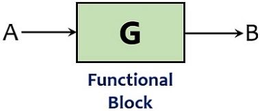
The transfer function of the cake shows the mathematical function of the element present as a cake.
Summing Point: The point in the block diagram representation where the multiple signals are compared is known equally the summing point.
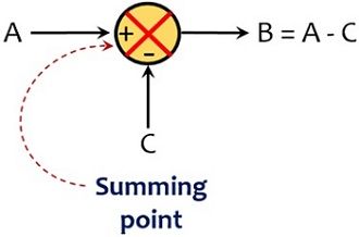
Take-off Signal: In a closed-loop system, part of the output is fed back to the input that acts as feedback for the system. So, the take-off point is that betoken from where a portion of the signal is taken equally feedback for the arrangement.
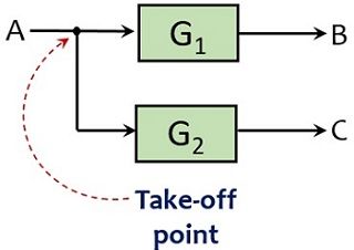
It is noteworthy at the fourth dimension of drawing the block diagram of a control system that the interconnection of blocks, summing points, and have-off points must be washed exactly in the way in which the elements are nowadays in the practical system.
The elements in the block diagram are continued using lines or branches. While arrowheads represent the management of flow of signal inside the block as the betoken flows only in a unidirectional path.
Thus nosotros can say the block diagram is a unilateral illustration of the arrangement.
Canonical form of Control System
We know that a airtight-loop organization uses a feedback loop thus is considered meliorate than the open-loop system.
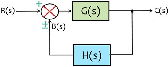
A cake diagram representation in which at that place is only one forwards and feedback cake along with a single summing indicate and take-off point is the simplest grade of closed-loop control arrangement. It is also known as the canonical form of a closed-loop organization.
The effigy beneath shows a simple closed-loop organization: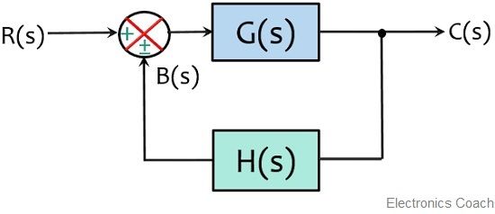
Instance of Control Organization
Let us accept an case in gild to sympathize how a practical system tin can be converted in the form of a block diagram.
Suppose we accept a liquid level arrangement as shown below and we take to represent this system in the form of a block diagram with the corresponding blocks for each chemical element.
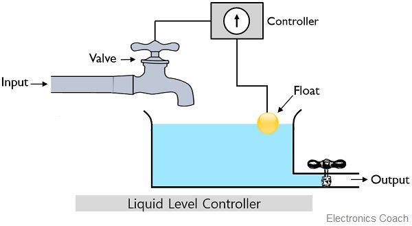
So, firstly we have to identify the overall elements present in the system. As we tin can see that the higher up system contains a controller, a valve, a water tank, and a float.
Basically, this organisation operates in a way that h2o from an outlet flows into the tank. All the same, a valve is present which can kickoff or stop the flow of water within the tank. This valve is controlled by the controller. Likewise, the system is incorporated with a float that senses the level of the water.
Basically the controller generates the signal regarding when to open or close the valve of the tank. But for this, the controller also needs to know that when information technology is required to be opened or closed.
So, the position of the bladder nowadays in the arrangement informs the controller about the level of water in the tank.
Suppose the level of h2o in the tank is below the level specified past the controller. So, the position of the float inside the tank notifies the controller that the valve must be kept open so that the water tin can period inside the tank.
Once the specified level is reached then the controller generates the signal and the valve will go airtight. The closure of the valve will automatically stop whatever farther catamenia of water inside the tank until the reception of the side by side command.
As we can encounter that the tank contains an outlet from where the water is allowed to get out the tank. Then, if h2o flows out from that outlet then the position of the float will automatically inform the controller that the water level is again decreased from the desired level.
So, the controller further sends a betoken to again open the valve and start the menses of liquid within the tank. In the fourth dimension being, the controller continuously monitors the position of the bladder inside the tank and accordingly sends the bespeak to the valve.
Thus from this discussion, nosotros can say that float acts every bit the feedback of this water level control system and the tank here is the process which is needed to be controlled by the controller.
Therefore, representing these elements in the class of a block diagram:

So, here the above figure shows the summing betoken, the functional blocks and the accept-off indicate of the above-discussed control arrangement.
This block diagram is simply made to explain you how the arrangement operates and what is the role of the feedback in a organisation. In the upcoming article, we will discuss the rules for cake diagram reduction of a complex system.
Source: https://electronicscoach.com/block-diagram-of-control-system.html
0 Response to "Draw Control System Block Diagram Online"
Postar um comentário